The Mac @TheMac
15 December, 12:32
From Middle English gayn, gain, gein (“profit, advantage”), from Old Norse gagn (“benefit, advantage, use”), from Proto-Germanic *gagną, *gaganą (“gain, profit", literally "return”), from Proto-Germanic *gagana (“back, against, in return”), a reduplication of Proto-Germanic *ga- (“with, together”), from Proto-Indo-European *ḱóm (“next to, at, with, along”). Cognate with Icelandic gagn (“gain, advantage, use”), Swedish gagn (“benefit, profit”), Danish gavn (“gain, profit, success”), Gothic 𐌲𐌰𐌲𐌴𐌹𐌲𐌰𐌽 (gageigan, “to gain, profit”), Old Norse gegn (“ready”), dialectal Swedish gen (“useful, noteful”), Latin cum (“with”); see gain-, again, against. Compare also Middle English gaynen, geinen (“to be of use, profit, avail”), Icelandic and Swedish gagna (“to avail, help”), Danish gavne (“to benefit”).

Notice: Undefined index: tg1tga_access in /home/admin/www/anonup.com/themes/default/apps/timeline/post.phtml on line 396
The Mac @TheMac
15 December, 12:33
In response The Mac to his Publication
The Middle English word was reinforced by Middle French gain (“gain, profit, advancement, cultivation”), from Old French gaaing, gaaigne, gaigne, a noun derivative of gaaignier (“to till, earn, win”), from Frankish *waidanjan (“to pasture, graze, hunt for food”), ultimately from Proto-Germanic *waiþiz, *waiþō, *waiþijō (“pasture, field, hunting ground”); compare Old High German weidōn, weidanōn (“to hunt, forage for food”) (Modern German Weide (“pasture”)), Old Norse veiða (“to catch, hunt”), Old English wǣþan (“to hunt, chase, pursue”). Related to wathe, wide.

Notice: Undefined index: tg1tga_access in /home/admin/www/anonup.com/themes/default/apps/timeline/post.phtml on line 396
The Mac @TheMac
15 December, 12:34
In response The Mac to his Publication
gain (third-person singular simple present gains, present participle gaining, simple past and past participle gained)

(transitive) To acquire possession of.

Notice: Undefined index: tg1tga_access in /home/admin/www/anonup.com/themes/default/apps/timeline/post.phtml on line 396
The Mac @TheMac
15 December, 12:36
In response The Mac to his Publication
(transitive, dated) To come off winner or victor in; to be successful in; to obtain by competition.

to gain a battle; to gain a case at law

(transitive) To increase.

(intransitive) To be more likely to catch or overtake an individual.

I'm gaining (on you).

gain ground

(transitive) To reach.

to gain the top of a mountain

Notice: Undefined index: tg1tga_access in /home/admin/www/anonup.com/themes/default/apps/timeline/post.phtml on line 396
The Mac @TheMac
15 December, 12:38
In response The Mac to his Publication
In glaciology, an ice cap is a mass of ice that covers less than 50,000 km2 (19,000 sq mi) of land area (usually covering a highland area). Larger ice masses covering more than 50,000 km2 (19,000 sq mi) are termed ice sheets.

Notice: Undefined index: tg1tga_access in /home/admin/www/anonup.com/themes/default/apps/timeline/post.phtml on line 396
The Mac @TheMac
15 December, 12:39
In response The Mac to his Publication
Ice sheets are bigger than ice shelves or alpine glaciers. Masses of ice covering less than 50,000 km2 are termed an ice cap.

Notice: Undefined index: tg1tga_access in /home/admin/www/anonup.com/themes/default/apps/timeline/post.phtml on line 396
The Mac @TheMac
15 December, 12:41
In response The Mac to his Publication
Mass crystallization is the nucleation and growth of a large number of usually small crystals (~10−3–10−1 cm) in one and the same area of space. Examples of it are the formation of metal ingots and kidney stones, the solidification of concrete, and the production of granulated fertilizers, medicines, sugar, and salt.

Notice: Undefined index: tg1tga_access in /home/admin/www/anonup.com/themes/default/apps/timeline/post.phtml on line 396
The Mac @TheMac
15 December, 12:43
In response The Mac to his Publication
At the present day, ultrafine soot particles have become the object of increasing attention due to their well-documented adverse effects on human health and climate. In particular, understanding soot nucleation is one of the most challenging problems toward a more controlled and cleaner combustion. Detailed information on the chemistry of nascent soot particles (NSPs) is expected to provide clues on the soot formation and growth reaction pathways. Herein, the early steps of soot formation in flames are addressed by investigating the chemical composition of NSPs and their molecular precursors by secondary ion mass spectrometry.

Notice: Undefined index: tg1tga_access in /home/admin/www/anonup.com/themes/default/apps/timeline/post.phtml on line 396
The Mac @TheMac
15 December, 12:44
In response The Mac to his Publication
Secondary-ion mass spectrometry (SIMS) is a technique used to analyze the composition of solid surfaces and thin films by sputtering the surface of the specimen with a focused primary ion beam and collecting and analyzing ejected secondary ions. The mass/charge ratios of these secondary ions are measured with a mass spectrometer to determine the elemental, isotopic, or molecular composition of the surface to a depth of 1 to 2 nm. Due to the large variation in ionization probabilities among elements sputtered from different materials, comparison against well-calibrated standards is necessary to achieve accurate quantitative results. SIMS is the most sensitive surface analysis technique, with elemental detection limits ranging from parts per million to parts per billion.

Notice: Undefined index: tg1tga_access in /home/admin/www/anonup.com/themes/default/apps/timeline/post.phtml on line 396
The Mac @TheMac
15 December, 12:46
In response The Mac to his Publication
In 1910 British physicist J. J. Thomson observed a release of positive ions and neutral atoms from a solid surface induced by ion bombardment.[1] Improved vacuum pump technology in the 1940s enabled the first prototype experiments on SIMS by Herzog and Viehböck[2] in 1949, at the University of Vienna, Austria.

Notice: Undefined index: tg1tga_access in /home/admin/www/anonup.com/themes/default/apps/timeline/post.phtml on line 396
The Mac @TheMac
15 December, 12:47
In response The Mac to his Publication
In the mid-1950s Honig constructed a SIMS instrument at RCA Laboratories in Princeton, New Jersey.[3] Then in the early 1960s two SIMS instruments were developed independently.

Notice: Undefined index: tg1tga_access in /home/admin/www/anonup.com/themes/default/apps/timeline/post.phtml on line 396
The Mac @TheMac
15 December, 12:47
In response The Mac to his Publication
One was an American project, led by Liebel and Herzog, which was sponsored by NASA at GCA Corp, Massachusetts, for analyzing moon rocks,[4] the other at the University of Paris-Sud in Orsay by R. Castaing for the PhD thesis of G. Slodzian.[5] These first instruments were based on a magnetic double focusing sector field mass spectrometer and used argon for the primary beam ions.

Notice: Undefined index: tg1tga_access in /home/admin/www/anonup.com/themes/default/apps/timeline/post.phtml on line 396
The Mac @TheMac
15 December, 12:48
In response The Mac to his Publication
In the 1970s, K. Wittmaack and C. Magee developed SIMS instruments equipped with quadrupole mass analyzers.[6][7] Around the same time, A. Benninghoven introduced the method of static SIMS, where the primary ion current density is so small that only a negligible fraction (typically 1%) of the first surface layer is necessary for surface analysis.[8] Instruments of this type use pulsed primary ion sources and time-of-flight mass spectrometers and were developed by Benninghoven, Niehuis and Steffens at the University of Münster, Germany and also by Charles Evans & Associates.

Notice: Undefined index: tg1tga_access in /home/admin/www/anonup.com/themes/default/apps/timeline/post.phtml on line 396
The Mac @TheMac
15 December, 12:49
In response The Mac to his Publication
The Castaing and Slodzian design was developed in the 1960s by the French company CAMECA S.A.S. and used in materials science and surface science.[citation needed] Recent developments are focusing on novel primary ion species like C60+, ionized clusters of gold and bismuth,[9] or large gas cluster ion beams (e.g., Ar700+).[10] The sensitive high-resolution ion microprobe (SHRIMP) is a large-diameter, double-focusing SIMS sector instrument based on the Liebl and Herzog design, and produced by Australian Scientific Instruments in Canberra, Australia

Notice: Undefined index: tg1tga_access in /home/admin/www/anonup.com/themes/default/apps/timeline/post.phtml on line 396
The Mac @TheMac
15 December, 12:51
In response The Mac to his Publication
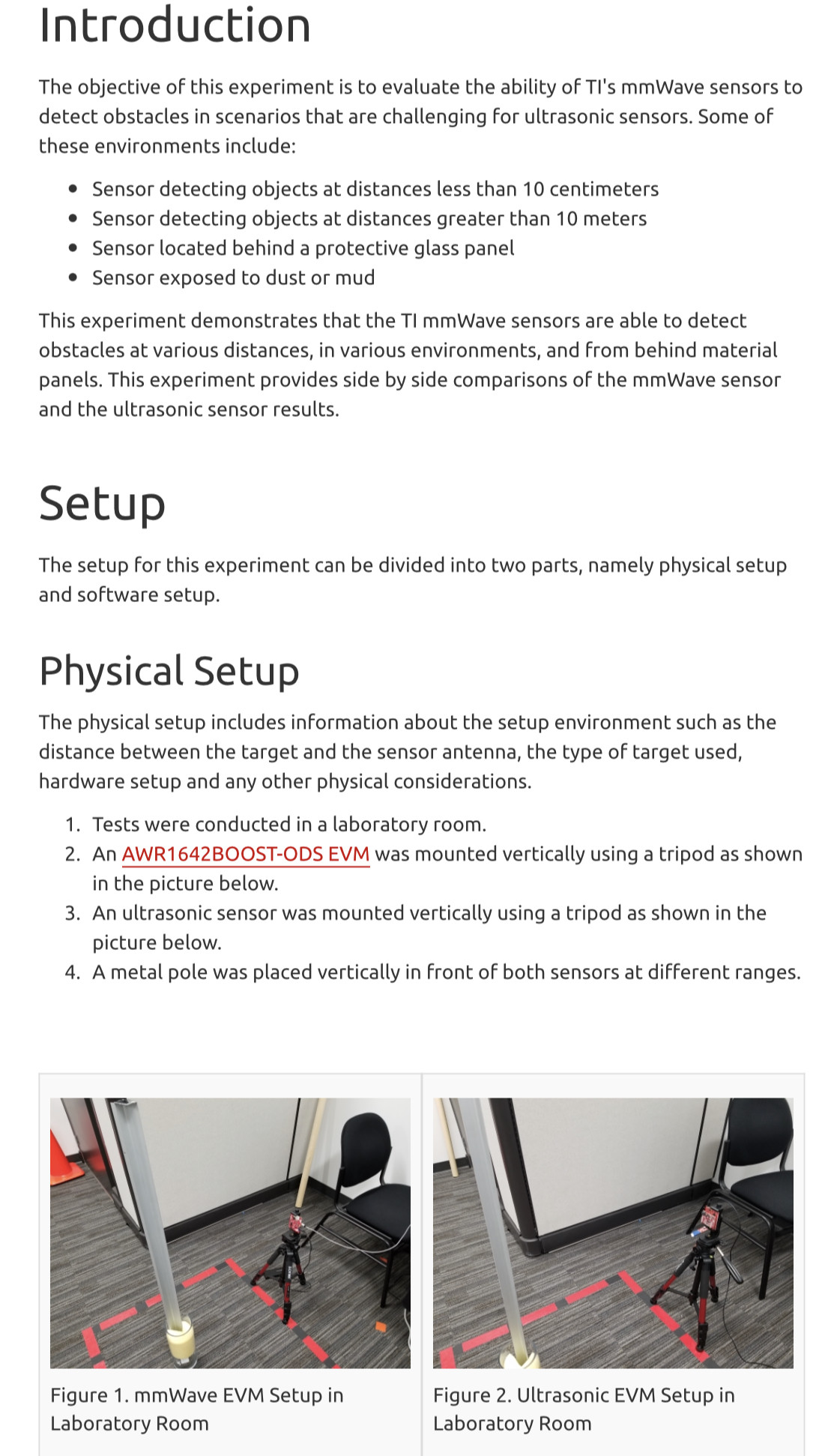
Depending on the SIMS type, there are three basic analyzers available: sector, quadrupole, and time-of-flight. A sector field mass spectrometer uses a combination of an electrostatic analyzer and a magnetic analyzer to separate the secondary ions by their mass-to-charge ratio. A quadrupole mass analyzer separates the masses by resonant electric fields, which allow only the selected masses to pass through. The time of flight mass analyzer separates the ions in a field-free drift path according to their velocity. Since all ions possess the same kinetic energy the velocity and therefore time of flight varies according to mass. It requires pulsed secondary ion generation using either a pulsed primary ion gun or a pulsed secondary ion extraction. It is the only analyzer type able to detect all generated secondary ions simultaneously, and is the standard analyzer for static SIMS instruments.

Notice: Undefined index: tg1tga_access in /home/admin/www/anonup.com/themes/default/apps/timeline/post.phtml on line 396
The Mac @TheMac
15 December, 12:57
In response The Mac to his Publication
The magnetic sector mass spectrometer causes a physical separation of ions of a different mass-to-charge ratio. The physical separation of the secondary ions is caused by the Lorentz force when the ions pass through a magnetic field that is perpendicular to the velocity vector of the secondary ions. The Lorentz force states that a particle will experience a force

Notice: Undefined index: tg1tga_access in /home/admin/www/anonup.com/themes/default/apps/timeline/post.phtml on line 396
The Mac @TheMac
15 December, 01:01
In response The Mac to his Publication
NanoSIMS can capture the spatial variability of isotopic and elemental measurements of sub-micron areas, grains or inclusions from geological, materials science and biological samples.[13] This instrument can characterise nanostructured materials with complex composition that are increasingly important candidates for energy generation and storage.

Notice: Undefined index: tg1tga_access in /home/admin/www/anonup.com/themes/default/apps/timeline/post.phtml on line 396
The Mac @TheMac
15 December, 01:02
In response The Mac to his Publication
NanoSIMS has also proved useful in studying cosmochemical issues, where samples of single, micro- or sub-micrometer-sized grains from meteorites as well as microtome sections prepared by the focused ion beam (FIB) technique can be analyzed. NanoSIMS can be combined with transmission electron microscopy (TEM) when using microtome or FIB sections. This combination allows for correlated mineralogical and isotopic studies in situ at a sub-micrometer scale.

It is particularly useful in materials research because of its high sensitivity at high mass resolution, which allow for trace element imaging and quantification.[14]

Notice: Undefined index: tg1tga_access in /home/admin/www/anonup.com/themes/default/apps/timeline/post.phtml on line 396
The Mac @TheMac
15 December, 01:04
In response The Mac to his Publication
Focused ion beam, also known as FIB, is a technique used particularly in the semiconductor industry, materials science and increasingly in the biological field for site-specific analysis, deposition, and ablation of materials. A FIB setup is a scientific instrument that resembles a scanning electron microscope (SEM). However, while the SEM uses a focused beam of electrons to image the sample in the chamber, a FIB setup uses a focused beam of ions instead. FIB can also be incorporated in a system with both electron and ion beam columns, allowing the same feature to be investigated using either of the beams. FIB should not be confused with using a beam of focused ions for direct write lithography (such as in proton beam writing). These are generally quite different systems where the material is modified by other mechanisms.

Notice: Undefined index: tg1tga_access in /home/admin/www/anonup.com/themes/default/apps/timeline/post.phtml on line 396
The Mac @TheMac
15 December, 01:12
In response The Mac to his Publication
X-ray crystallography is the experimental science determining the atomic and molecular structure of a crystal, in which the crystalline structure causes a beam of incident X-rays to diffract into many specific directions. By measuring the angles and intensities of these diffracted beams, a crystallographer can produce a three-dimensional picture of the density of electrons within the crystal. From this electron density, the mean positions of the atoms in the crystal can be determined, as well as their chemical bonds, their crystallographic disorder, and various other information.

Notice: Undefined index: tg1tga_access in /home/admin/www/anonup.com/themes/default/apps/timeline/post.phtml on line 396
The Mac @TheMac
15 December, 01:18
In response The Mac to his Publication

Notice: Undefined index: tg1tga_access in /home/admin/www/anonup.com/themes/default/apps/timeline/post.phtml on line 396
The Mac @TheMac
15 December, 01:40
In response The Mac to his Publication

Notice: Undefined index: tg1tga_access in /home/admin/www/anonup.com/themes/default/apps/timeline/post.phtml on line 396
The Mac @TheMac
15 December, 01:56
In response The Mac to his Publication
A microprobe is an instrument that applies a stable and well-focused beam of charged particles (electrons or ions) to a sample.

Notice: Undefined index: tg1tga_access in /home/admin/www/anonup.com/themes/default/apps/timeline/post.phtml on line 396
The Mac @TheMac
15 December, 01:58
In response The Mac to his Publication
When the primary beam consists of accelerated electrons, the probe is termed an electron microprobe, when the primary beam consists of accelerated ions, the term ion microprobe is used. The term microprobe may also be applied to optical analytical techniques, when the instrument is set up to analyse micro samples or micro areas of larger specimens. Such techniques include micro Raman spectroscopy, micro infrared spectroscopy and micro LIBS. All of these techniques involve modified optical microscopes to locate the area to be analysed, direct the probe beam and collect the analytical signal.

A laser microprobe is a mass spectrometer that uses ionization by a pulsed laser and subsequent mass analysis of the generated ions.

Notice: Undefined index: tg1tga_access in /home/admin/www/anonup.com/themes/default/apps/timeline/post.phtml on line 396
The Mac @TheMac
15 December, 02:00
In response The Mac to his Publication
Scientists use this beam of charged particles to determine the elemental composition of solid materials (minerals, glasses, metals).[4] The chemical composition of the target can be found from the elemental data extracted through emitted X-rays (in the case where the primary beam consists of charged electrons) or measurement of an emitted secondary beam of material sputtered from the target (in the case where the primary beam consists of charged ions).

Notice: Undefined index: tg1tga_access in /home/admin/www/anonup.com/themes/default/apps/timeline/post.phtml on line 396
The Mac @TheMac
15 December, 02:01
In response The Mac to his Publication
When the ion energy is in the range of a few tens of keV (kilo-electronvolt) these microprobes are usually called FIB (Focused ion beam). An FIB makes a small portion of the material into a plasma; the analysis is done by the same basic techniques as the ones used in mass spectrometry.

Notice: Undefined index: tg1tga_access in /home/admin/www/anonup.com/themes/default/apps/timeline/post.phtml on line 396
The Mac @TheMac
15 December, 02:03
In response The Mac to his Publication
When the ion energy is higher, hundreds of keV to a few MeV (mega-electronvolt) they are called nuclear microprobes. Nuclear microprobes are extremely powerful tools that utilize ion beam analysis techniques as microscopies with spot sizes in the micro-/nanometre range. These instruments are applied to solve scientific problems in a diverse range of fields, from microelectronics to biomedicine. In addition to the development of new ways to exploit these probes as analytical tools (this application area of the nuclear microprobes is called nuclear microscopy), strong progress has been made in the area of materials modification recently (most of which can be described as PBW, proton beam writing)

Notice: Undefined index: tg1tga_access in /home/admin/www/anonup.com/themes/default/apps/timeline/post.phtml on line 396
The Mac @TheMac
15 December, 02:06
In response The Mac to his Publication
The nuclear microprobe's[5] beam is usually composed of protons and alpha particles. Some of the most advanced nuclear microprobes have beam energies in excess of 2 MeV. This gives the device very high sensitivity to minute concentrations of elements, around 1 ppm at beam sizes smaller than 1 micrometer. This elemental sensitivity exists because when the beam interacts with the a sample it gives off characteristic X-rays of each element present in the sample. This type of detection of radiation is called PIXE. Other analysis techniques are applied to nuclear microscopy including Rutherford backscattering(RBS), STIM, etc.

Notice: Undefined index: tg1tga_access in /home/admin/www/anonup.com/themes/default/apps/timeline/post.phtml on line 396
The Mac @TheMac
15 December, 02:07
In response The Mac to his Publication
Another use for microprobes is the production of micro and nano sized devices, as in microelectromechanical systems and nanoelectromechanical systems.[6] The advantage that microprobes have over other lithography processes is that a microprobe beam can be scanned or directed over any area of the sample. This scanning of the microprobe beam can be imagined to be like using a very fine tipped pencil to draw your design on a paper or in a drawing program. Traditional lithography processes use photons which cannot be scanned and therefore masks are needed to selectively expose your sample to radiation. It is the radiation that causes changes in the sample, which in turn allows scientists and engineers to develop tiny devices such as microprocessors, accelerometers (like in most car safety systems), etc.

Notice: Undefined index: tg1tga_access in /home/admin/www/anonup.com/themes/default/apps/timeline/post.phtml on line 396
The Mac @TheMac
15 December, 02:10
In response The Mac to his Publication
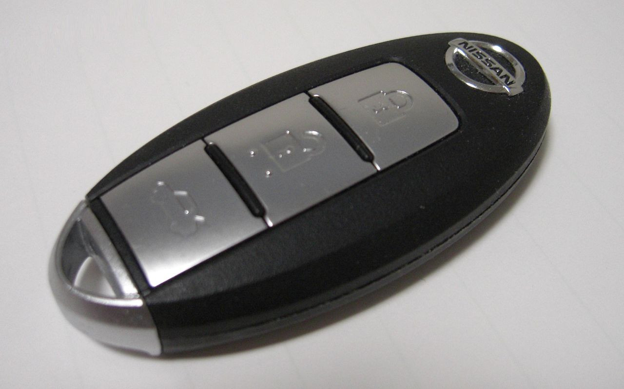
A smart key is an electronic access and authorization system that is available either as standard equipment, or as an option in several car designs. It was first developed by Siemens in 1995 and introduced by Mercedes-Benz under the name "Keyless-Go" in 1998 on the W220 S-Class, after the design patent was filed by Daimler-Benz on May 17, 1997.

Notice: Undefined index: tg1tga_access in /home/admin/www/anonup.com/themes/default/apps/timeline/post.phtml on line 396
The Mac @TheMac
15 December, 02:11
In response The Mac to his Publication
The smart key allows the driver to keep the key fob pocketed when unlocking, locking and starting the vehicle. The key is identified via one of several antennas in the car's bodywork and a radio pulse generator in the key housing. Depending on the system, the vehicle is automatically unlocked when a button or sensor on the door handle or trunk release is pressed. Vehicles with a smart-key system have a mechanical backup, usually in the form of a spare key blade supplied with the vehicle. Some manufacturers hide the backup lock behind a cover for styling.

Notice: Undefined index: tg1tga_access in /home/admin/www/anonup.com/themes/default/apps/timeline/post.phtml on line 396
The Mac @TheMac
15 December, 02:14
In response The Mac to his Publication

Notice: Undefined index: tg1tga_access in /home/admin/www/anonup.com/themes/default/apps/timeline/post.phtml on line 396
The Mac @TheMac
15 December, 02:17
In response The Mac to his Publication
blade; plural noun: blades; noun: blade bone; plural noun: blade bones
1.
the flat cutting edge of a knife, saw, or other tool or weapon.

"cut cleanly using a sharp blade"

LITERARY
a sword.

AUSTRALIAN•NEW ZEALAND
hand shears used in sheep shearing.

Notice: Undefined index: tg1tga_access in /home/admin/www/anonup.com/themes/default/apps/timeline/post.phtml on line 396
The Mac @TheMac
15 December, 02:21
In response The Mac to his Publication

Notice: Undefined index: tg1tga_access in /home/admin/www/anonup.com/themes/default/apps/timeline/post.phtml on line 396
The Mac @TheMac
15 December, 02:23
In response The Mac to his Publication

Notice: Undefined index: tg1tga_access in /home/admin/www/anonup.com/themes/default/apps/timeline/post.phtml on line 396
The Mac @TheMac
15 December, 02:27
In response The Mac to his Publication
https://en.m.wikipedia.org...

https://en.m.wikipedia.org...

https://en.m.wikipedia.org...

Technically, a material is under a state of compression, at some specific point and along a specific direction
x
x, if the normal component of the stress vector across a surface with normal direction
x
x is directed opposite to
x
x. If the stress vector itself is opposite to
x
x, the material is said to be under normal compression or pure compressive stress along
x
x. In a solid, the amount of compression generally depends on the direction
x
x, and the material may be under compression along some directions but under traction along others. If the stress vector is purely compressive and has the same magnitude for all directions, the material is said to be under isotropic or hydrostatic compression at that point. This is the only type of static compression that liquids and gases can bear.

Notice: Undefined index: tg1tga_access in /home/admin/www/anonup.com/themes/default/apps/timeline/post.phtml on line 396
The Mac @TheMac
15 December, 02:28
In response The Mac to his Publication
In a mechanical wave which is longitudinal, the medium is displaced in the wave's direction, resulting in areas of compression and rarefaction

Notice: Undefined index: tg1tga_access in /home/admin/www/anonup.com/themes/default/apps/timeline/post.phtml on line 396
The Mac @TheMac
15 December, 02:29
In response The Mac to his Publication
A mechanical wave is a wave that is an oscillation of matter, and therefore transfers energy through a medium.[1] While waves can move over long distances, the movement of the medium of transmission—the material—is limited. Therefore, the oscillating material does not move far from its initial equilibrium position. Mechanical waves transport energy. This energy propagates in the same direction as the wave. Any kind of wave (mechanical or electromagnetic) has a certain energy. Mechanical waves can be produced only in media which possess elasticity and inertia.

Notice: Undefined index: tg1tga_access in /home/admin/www/anonup.com/themes/default/apps/timeline/post.phtml on line 396
The Mac @TheMac
15 December, 02:30
In response The Mac to his Publication
A wave requires an initial energy input. Once this initial energy is added, the wave travels through the medium until all its energy is transferred. In contrast, electromagnetic waves require no medium, but can still travel through one.

One important property of mechanical waves is that their amplitudes are measured in an unusual way, displacement divided by (reduced) wavelength. When this gets comparable to unity, significant nonlinear effects such as harmonic generation may occur, and, if large enough, may result in chaotic effects. For example, waves on the surface of a body of water break when this dimensionless amplitude exceeds 1, resulting in a foam on the surface and turbulent mixing.

There are three types of mechanical waves: transverse waves, longitudinal waves, and surface waves, etc. Some of the most common examples of mechanical waves are water waves, sound waves, and seismic waves.

Notice: Undefined index: tg1tga_access in /home/admin/www/anonup.com/themes/default/apps/timeline/post.phtml on line 396
The Mac @TheMac
15 December, 02:32
In response The Mac to his Publication
Transverse wave is the form of wave in which particles of medium vibrates about their mean position perpendicular to the direction of the motion of the wave.

To see an example, move an end of a Slinky (whose other end is fixed) to the left-and-right of the Slinky, as opposed to to-and-fro.[2] Light also has properties of a transverse wave, although it is an electromagnetic wave.[3]

Notice: Undefined index: tg1tga_access in /home/admin/www/anonup.com/themes/default/apps/timeline/post.phtml on line 396
The Mac @TheMac
15 December, 02:33
In response The Mac to his Publication
Longitudinal waves cause the medium to vibrate parallel to the direction of the wave. It consists of multiple compressions and rarefactions. The rarefaction is the farthest distance apart in the longitudinal wave and the compression is the closest distance together. The speed of the longitudinal wave is increased in higher index of refraction, due to the closer proximity of the atoms in the medium that is being compressed. Sound is a longitudinal wave.

Notice: Undefined index: tg1tga_access in /home/admin/www/anonup.com/themes/default/apps/timeline/post.phtml on line 396
The Mac @TheMac
15 December, 02:34
In response The Mac to his Publication
This type of wave travels along the surface or interface between two media. An example of a surface wave would be waves in a pool, or in an ocean, lake, or any other type of water body. There are two types of surface waves, namely Rayleigh waves and Love waves.

Rayleigh waves, also known as ground roll, are waves that travel as ripples with motion similar to those of waves on the surface of water. Such waves are much slower than body waves, at roughly 90% of the velocity of bulk waves[clarify] for a typical homogeneous elastic medium. Rayleigh waves have energy losses only in two dimensions and are hence more destructive in earthquakes than conventional bulk waves, such as P-waves and S-waves, which lose energy in all three directions.

A Love wave is a surface wave having horizontal waves that are shear or transverse to the direction of propagation. They usually travel slightly faster than Rayleigh waves, at about 90% of the body wave velocity, and have the largest amplitude.

Notice: Undefined index: tg1tga_access in /home/admin/www/anonup.com/themes/default/apps/timeline/post.phtml on line 396
The Mac @TheMac
15 December, 02:39
In response The Mac to his Publication
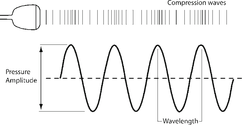
Amplitude refers to the strength of the sound wave, as represented by the height of the wave (see Fig. 1.1a). Amplitude is measured in units of pressure, Mega Pascals (MPa). Power of the sound wave, refers to the total amount of energy in the ultrasound beam, and is measured in watts

Notice: Undefined index: tg1tga_access in /home/admin/www/anonup.com/themes/default/apps/timeline/post.phtml on line 396
The Mac @TheMac
15 December, 02:41
In response The Mac to his Publication
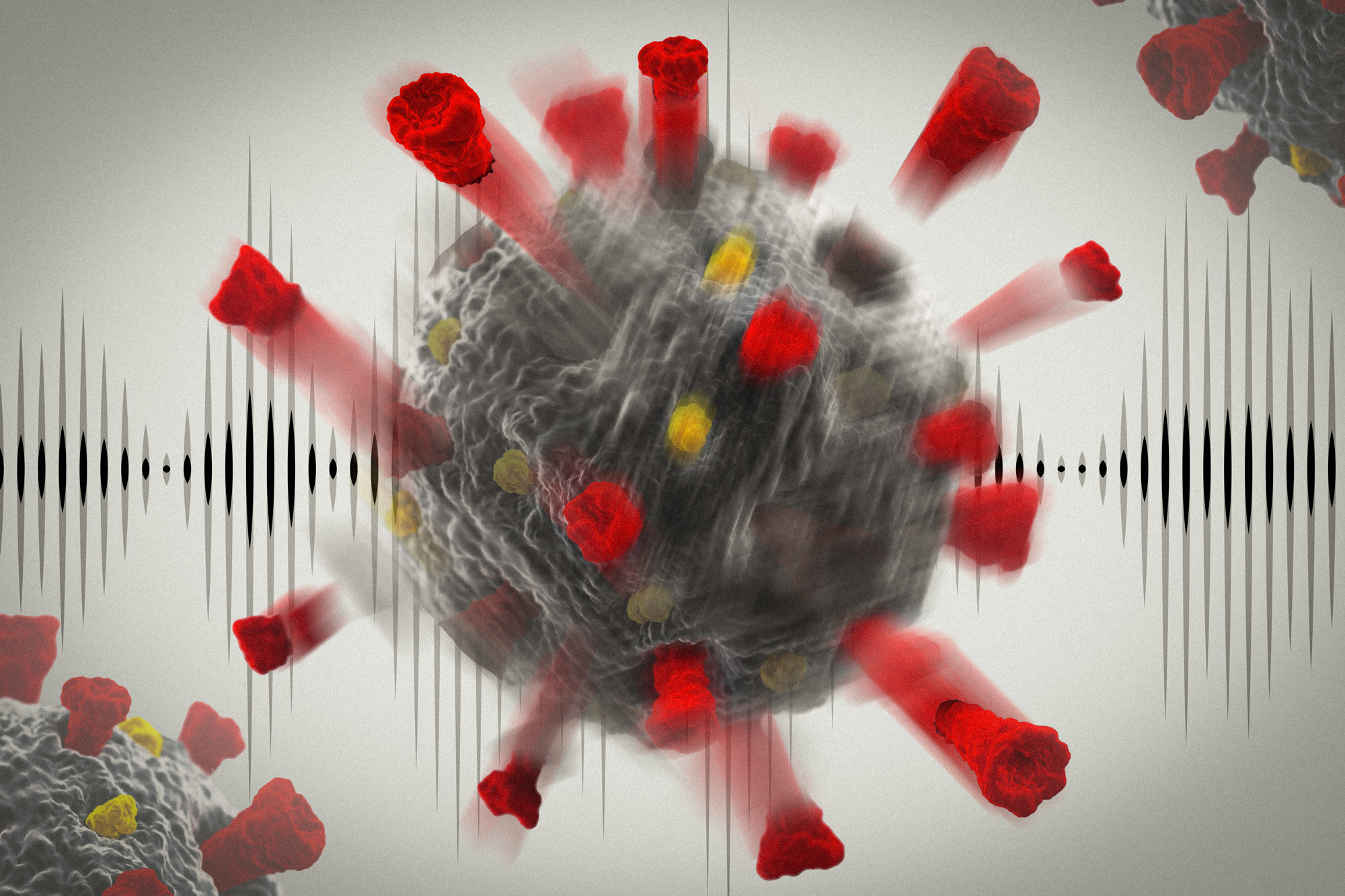
Ultrasound has potential to damage coronaviruses, study finds
Simulations show ultrasound waves at medical imaging frequencies can cause the virus’ shell and spikes to collapse and rupture.
Watch Video
Jennifer Chu | MIT News Office
Publication Date: March 16, 2021 ?

Notice: Undefined index: tg1tga_access in /home/admin/www/anonup.com/themes/default/apps/timeline/post.phtml on line 396
The Mac @TheMac
15 December, 02:43
In response The Mac to his Publication
https://www.osapublishing....

Holographic optical tweezers were used to show the interaction between a strongly focused laser beam and magnetic nanoparticles in ferrofluid. When the light intensity was high enough, magnetic nanoparticles were removed from the beam center and formed a dark ring. The same behavior was observed when focusing vortex or Bessel beams. The interactions between two or more separated rings of magnetic nanoparticles created by independent optical traps were also observed.

Notice: Undefined index: tg1tga_access in /home/admin/www/anonup.com/themes/default/apps/timeline/post.phtml on line 396
The Mac @TheMac
15 December, 03:02
In response The Mac to his Publication

Notice: Undefined index: tg1tga_access in /home/admin/www/anonup.com/themes/default/apps/timeline/post.phtml on line 396
The Mac @TheMac
15 December, 03:04
In response The Mac to his Publication

Notice: Undefined index: tg1tga_access in /home/admin/www/anonup.com/themes/default/apps/timeline/post.phtml on line 396
The Mac @TheMac
15 December, 03:06
In response The Mac to his Publication

Notice: Undefined index: tg1tga_access in /home/admin/www/anonup.com/themes/default/apps/timeline/post.phtml on line 396
The Mac @TheMac
15 December, 03:08
In response The Mac to his Publication
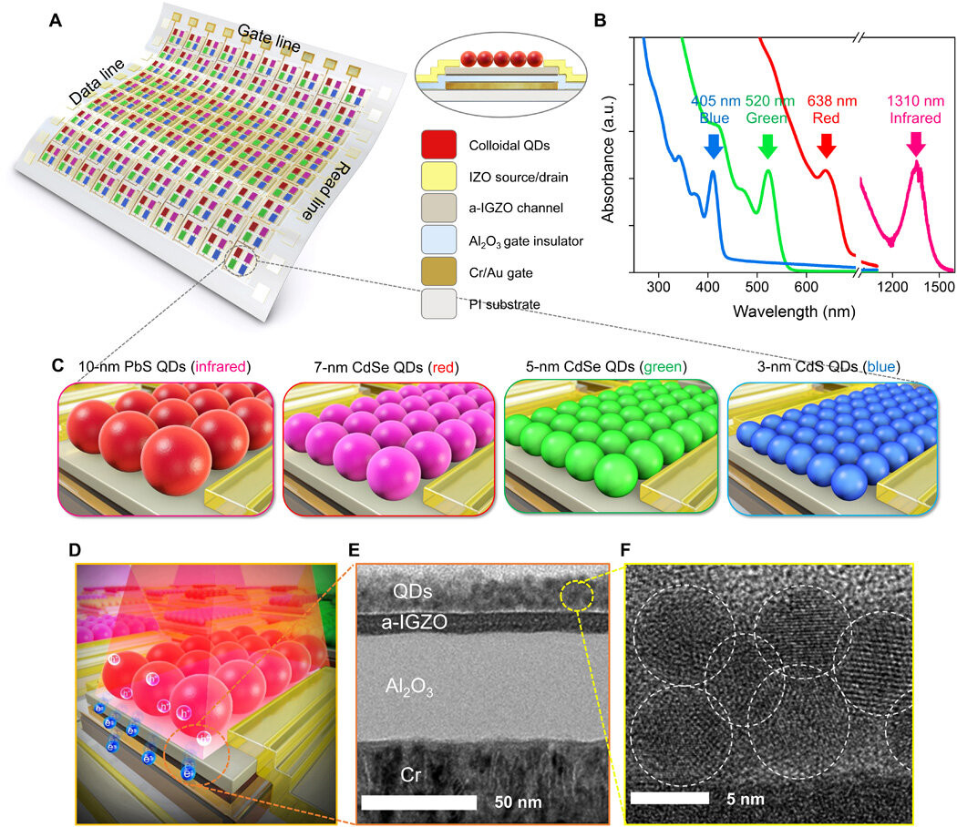
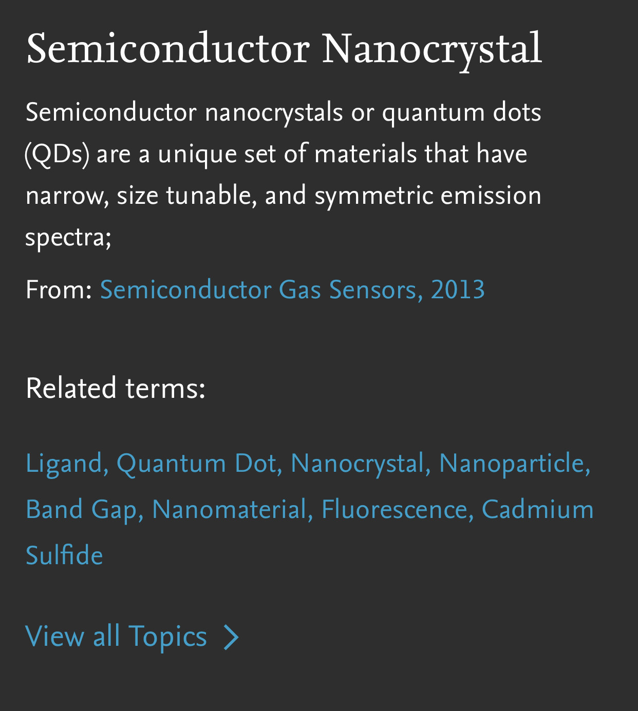
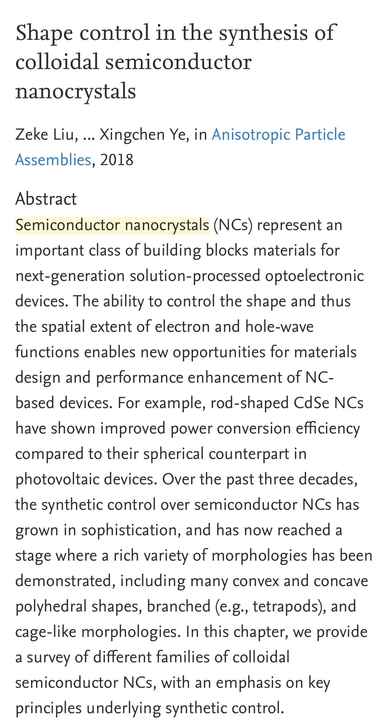
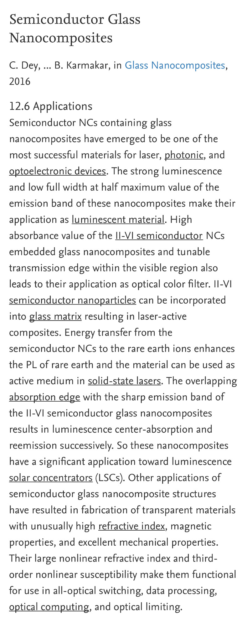
Semiconductor nanocrystal quantum dots (QDs) are excellent fluorophores for sensors because of their extraordinary optical properties. They have high thermal and photochemical stability compared to organic dyes or fluorescent proteins and are extremely bright due to their large molar cross-sections.

Notice: Undefined index: tg1tga_access in /home/admin/www/anonup.com/themes/default/apps/timeline/post.phtml on line 396
The Mac @TheMac
15 December, 05:25
In response The Mac to his Publication

Notice: Undefined index: tg1tga_access in /home/admin/www/anonup.com/themes/default/apps/timeline/post.phtml on line 396
The Mac @TheMac
15 December, 05:27
In response The Mac to his Publication

Notice: Undefined index: tg1tga_access in /home/admin/www/anonup.com/themes/default/apps/timeline/post.phtml on line 396
The Mac @TheMac
15 December, 05:28
In response The Mac to his Publication

Notice: Undefined index: tg1tga_access in /home/admin/www/anonup.com/themes/default/apps/timeline/post.phtml on line 396
The Mac @TheMac
15 December, 05:30
In response The Mac to his Publication

Notice: Undefined index: tg1tga_access in /home/admin/www/anonup.com/themes/default/apps/timeline/post.phtml on line 396
The Mac @TheMac
15 December, 05:33
In response The Mac to his Publication

Notice: Undefined index: tg1tga_access in /home/admin/www/anonup.com/themes/default/apps/timeline/post.phtml on line 396
Only people mentioned by TheMac in this post can reply
The Mac @TheMac
15 December, 05:40
In response The Mac to his Publication
A related application is in laser ultrasonic inspection. Defects in industrial material processing such as welding have characteristic ultrasonic signatures. The part under test is pinged by a pulsed laser and a probe laser is reflected from the part. As the part is shaken by the ultrasound, speckle in the reflected beam vibrates. A photorefractive recording is made of the speckle beam.

Notice: Undefined index: tg1tga_access in /home/admin/www/anonup.com/themes/default/apps/timeline/post.phtml on line 396
The Mac @TheMac
15 December, 05:40
In response The Mac to his Publication
Electrodes are placed on the photorefractive material, so that any optically induced currents can be detected. If the speckle pattern is not moving, or is moving more slowly than the speed of response of the photorefractive material, the photorefractive grating will be essentially at steady state: the drift currents balance the diffusion currents so there is no net current. There is no signal as the part moves through the process line. However, if the speckle beam is moving faster than the response time of the material, it will move photoexcited charge back and forth past the quasistatic grating and generate a net current for detection via the electrodes.

Notice: Undefined index: tg1tga_access in /home/admin/www/anonup.com/themes/default/apps/timeline/post.phtml on line 396